Introduction
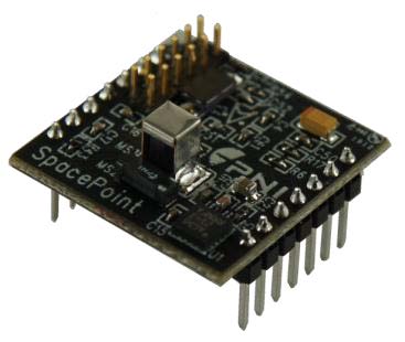
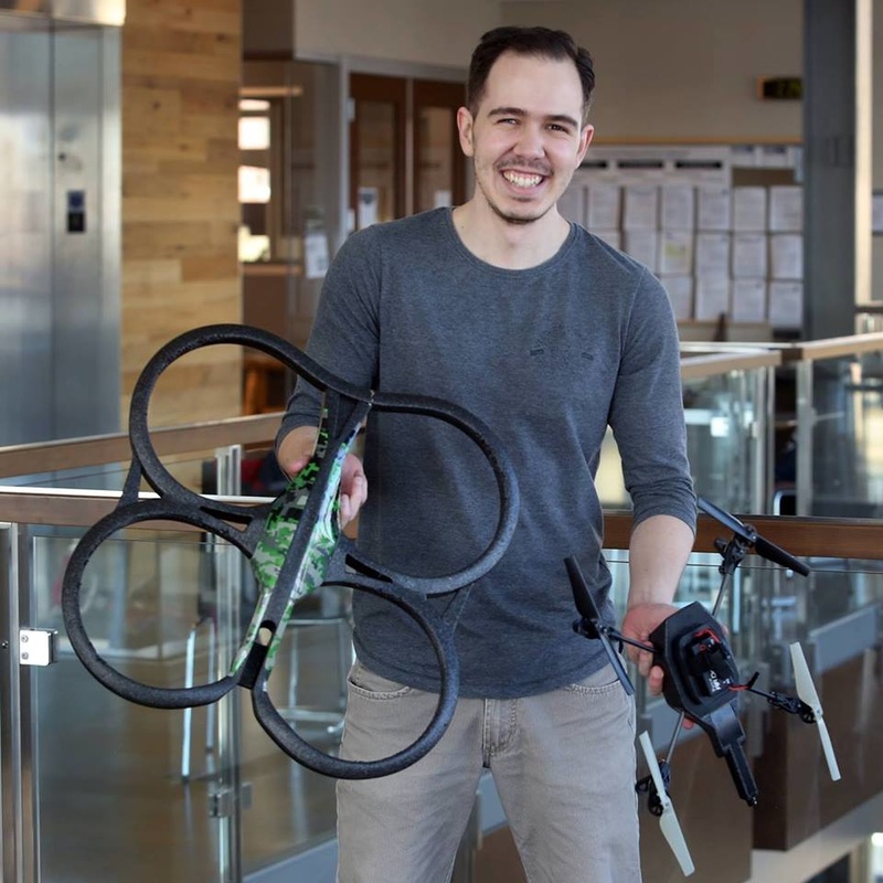
I have found the 9 degrees of freedom (DOF) IMU (Inertial Measurement Unit) SpacePoint Scout in my lab, and I decided to play with it. My initial plan was apply the knowledge in estimation to do some sensor fusion example. It turns out this IMU has an algorithm that delivers the measurements already fused. IMUs are used in all kind of devices, from car and airplanes, to smartphones and game controllers. The first time that I used and IMU was when I was building my own quadrotor a couple of years ago. For this tutorial, I am going to show how to acquire information from this IMU, and represent the output in an meaningful way using C++ and OpenGL.
What does it measure?
We need to know the DOF of our IMU. In our case we have 9DOF, meaning that we have 3 different sensors: accelerometer, gyroscope and magnetometer. Each of these snesors are acquiring measurements in the x,y and z axis. However, it is usual to see 6DOF IMUs using accelerometers and gyroscopes only. The overall fusion of these measurements will give an insight of the inclination of a particular surface or body, the redundancy of sensors give a better estimation of such inclination, by creating a synergy among sensors.
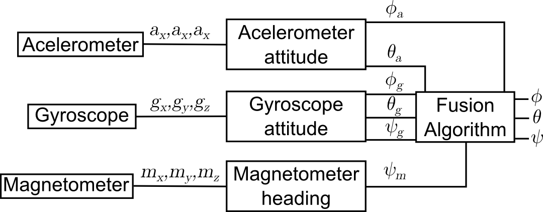
The previous is one of the many representations architectures that can be implemented to fuse the different measurements. If a Kalman Filter is used, it is most likely that the biases are also take into account in the overall fusion. Our IMU returns the data normalized from the quaternion calculation $R[-1,1]$. For our purpose we are converting this quaternions into a meaningful and understandable data, in this case, to Euler angles. They are different representations that can be used, and some of them can lead to singularities. Since some inverse trigonometric functions are not defined in the range $[0,360]$. For this reason, we are using the following representation to find the angles. \begin{align*} \phi&= asin(-2(q_y \times q_z- q_w\times q_y))\\ \end{align*} \begin{align*} \theta&= atan_2(2(q_y \times q_z+q_w \times q_x),q_w^2-q_x^2-q_y^2+ q_z^2)\\ \end{align*} \begin{align*} \psi&= atan_2(2(q_x \times q_y+q_w \times q_z),q_w^2+q_x^2-q_y^2- q_zq_z^2)\\ \end{align*} Where pitch ($\theta$), roll($\phi$) and yaw($\psi$) are the Euler angles. Retrieving the data
An Arduino UNO was used as a bridge between the Laptot and the IMU. The SpacePoint Scout can deliver the data using an UART or I2C communication. For this particular post the I2C was chosen. The datasheet of the IMU can be found below.
One of the problems that I faced at first it was establishing the I2C communication. The datasheet states that the address of the IMU is HwADDR = 0x18, which in binary is "0001 1001". Also the address to access the data is HwADDR+1, which it becomes in 0x19, 0x20, 0x21 and so on. The previous communication is including the 8th bit, that is commonly used to R/W purposes. To solve this problem, only the first seven bits are used, which gives as a result 0x0C, represented in binary as "00 1100". The following image illustrates the previous example. 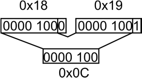
The Code
The code will send commands in both directions. To display the IMU data, I used a C++ program that sends bidirectional information. An "A" is sent to the Arduino to tell that is ready to received data from the IMU, the quaternions are acquired, scaled and converted into Euler angles using the previous formulas. For visualization purposes, I have used a small window that displays the inclination of the IMU, I used OpenGL to accomplish such task, you can find the Arduino and C++ code below, also you can download it and compile it.
Space_Point.ino
/*
IMU SpacePoint Scout + Arduino + C++

Arduino UNO gets the quaternions qx,qy,qz and qw
and sends it to the computer when an "A" is pre-
sent in the Serial Port.

The circuit:
ARDUINO UNO    IMU
SCL  -------->  SCL
SDA  -------->  SDA
5V   -------->  Vin
GND  -------->  GND

By Andres F. Echeverri
http://allmechatronics.weebly.com/
*/

#include<Wire.h>
#include <stdio.h>
#include <stdarg.h>

/** Function retreived from http://playground.arduino.cc/Main/Printf
  * Similar to printf
*/
void p(char *fmt, ... )
{
  char buf[128]; //resulting string limited to 128 chars
  va_list args;
  va_start (args, fmt );
  vsnprintf(buf, 128, fmt, args);
  va_end (args);
  Serial.print(buf);
}

unsigned int Q_s[3];
char var;
/** Slave Address in 7 bits
  * (Removing the R/W bit).
*/
int SPC=0x0c;
void setup()
{
  Serial.begin(115200);
  Wire.begin();  //ST
  Wire.beginTransmission(SPC);  //HwADDR
  uint8_t succs=Wire.endTransmission(false);  //False end transmission
  Wire.write(0x31);  //0x31 According to the Datasheet
}

void loop()
{
  Wire.beginTransmission(SPC);
  Wire.requestFrom(SPC,8,false);

  int data_av=(Wire.available()/2);

  if (Serial.available()>0)
  {
    var=Serial.read();
    // If the "A" is read, the Uno will respond with the Quaternions data
    if(var=='A')
    {
      for (int i=0; i<data_av; i++)
      {
        // Read the LSB and MSB and put it form the number
        unsigned int Quaternion=Wire.read()<<8|Wire.read();
        Q_s[i]=Quaternion;
      }
    //Formats the number to send it through serial
    p("G;%05u;%05u;%05u;%05u;",Q_s[0],Q_s[1],Q_s[2],Q_s[3]);
    }
  }
}
Space_Point.cpp
/*
IMU SpacePoint Scout + Arduino + C++

Arduino UNO gets the quaternions qx,qy,qz and qw
and sends it to the computer when an "A" is pre-
sent in the Serial Port.

The circuit:
ARDUINO UNO    IMU
SCL  -------->  SCL
SDA  -------->  SDA
5V   -------->  Vin
GND  -------->  GND

By Andres F. Echeverri
http://allmechatronics.weebly.com/
*/

#include <stdio.h>
#include <math.h>
#include <stdlib.h>
#include <string.h>
#include <unistd.h>
#include <fstream>
#include <sstream>
#include <iostream>
#include <cmath>
#include <vector>
#include <GL/glut.h>

using namespace std;

void display();

vectorquat_vect(2,0);
//Selecting port for the Arduino
char serialPortFilename[] = "/dev/ttyACM0";
//Writing Port
FILE *serPort_w=fopen(serialPortFilename,"w");
//Reading Port
FILE *serPort_r=fopen(serialPortFilename,"r");
char *parameter=0;
char s[1];

/** Function that gets the quaternions and returns a
  * vector with the euler angles.
*/
vector quat_euler(double &qx, double &qy, double &qz, double &qw)
{
  double rad_deg=180 / M_PI;
  vectorretVector(3,0);
  // yaw
  retVector[0] = atan2(2.0 * (qx * qy + qw * qz), qw * qw + qx * qx - qy * qy - qz * qz);
  // pitch
  retVector[1] = asin(-2.0 * (qx * qz - qw * qy));
  // roll
  retVector[2] = atan2(2.0 * (qy * qz + qw * qx), qw * qw - qx * qx - qy * qy + qz * qz);


  retVector[0] = retVector[0] * rad_deg;
  retVector[1] = retVector[1] * rad_deg;
  retVector[2] = retVector[2] * rad_deg;

  return retVector;
}

/** Function to normalize the quaternions.
  * in R[-1,1].
  * Refer to page 12 of the Datasheet.
*/
double scaled_quaternion(int quaternion)
{
        double off_s=32768.0;
        double Q_s=(quaternion-off_s)/off_s;
        return Q_s;
}

/** Function that establish communication
  * With the arduino and process the qua-
  * ternions.
*/
vector IMU_DATA()
{
        int size_v=26;
        char writeBuffer[1]={'A'};
        char readBuffer[size_v];

        fwrite(writeBuffer, sizeof(char), 1, serPort_w);
        fflush(serPort_w);

        usleep(10000);

        fread(readBuffer,sizeof(char),size_v,serPort_r);

        if(sizeof(readBuffer) != 0)
        {
                // "G" is the first position of the transmision buffer
                if(readBuffer[0]=='G')
                {
                        parameter=strtok(readBuffer,s);
                        int QX=atoi(strtok(0,s));
                        int QY=atoi(strtok(0,s));
                        int QZ=atoi(strtok(0,s));
                        int QW=atoi(strtok(0,s));

                        double QD_x=scaled_quaternion(QX);
                        double QD_y=scaled_quaternion(QY);
                        double QD_z=scaled_quaternion(QZ);
                        double QD_w=scaled_quaternion(QW);

                        quat_vect=quat_euler(QD_x,QD_y,QD_z,QD_w);
                }
        }
  return quat_vect;
}

/** Function that creates a cube
  * More information in
  * http://xyzmind.blogspot.com/2012/08/setup-eclipse-c-and-opengl-support-on.html
*/
void display()
{
        //Clear screen and Z-buffer
        glClear(GL_COLOR_BUFFER_BIT|GL_DEPTH_BUFFER_BIT);

        //Reset transformations
        glLoadIdentity();

        vector IMU_euler_ang=IMU_DATA();

        // Rotate according to IMU
        glRotatef(  quat_vect[0], 0.0, 1.0, 0.0 );
        glRotatef(  quat_vect[1], 0.0, 0.0, 1.0 );
        glRotatef( -quat_vect[2], 1.0, 0.0, 0.0 );

        //Multi-colored side - FRONT
        glBegin(GL_POLYGON);

        glColor3f( 1.0, 0.0, 0.0 );     glVertex3f(  0.5, -0.5, -0.5 ); // P1 is red
        glColor3f( 0.0, 1.0, 0.0 );     glVertex3f(  0.5,  0.5, -0.5 ); // P2 is green
        glColor3f( 0.0, 0.0, 1.0 );     glVertex3f( -0.5,  0.5, -0.5 ); // P3 is blue
        glColor3f( 1.0, 0.0, 1.0 );     glVertex3f( -0.5, -0.5, -0.5 ); // P4 is purple


        glEnd();

        // White side - BACK
        glBegin(GL_POLYGON);
        glColor3f(   1.0,  1.0, 1.0 );
        glVertex3f(  0.5, -0.5, 0.5 );
        glVertex3f(  0.5,  0.5, 0.5 );
        glVertex3f( -0.5,  0.5, 0.5 );
        glVertex3f( -0.5, -0.5, 0.5 );
        glEnd();

        // Purple side - RIGHT
        glBegin(GL_POLYGON);
        glColor3f(  1.0,  0.0,  1.0 );
        glVertex3f( 0.5, -0.5, -0.5 );
        glVertex3f( 0.5,  0.5, -0.5 );
        glVertex3f( 0.5,  0.5,  0.5 );
        glVertex3f( 0.5, -0.5,  0.5 );
        glEnd();

        // Green side - LEFT
        glBegin(GL_POLYGON);
        glColor3f(   0.0,  1.0,  0.0 );
        glVertex3f( -0.5, -0.5,  0.5 );
        glVertex3f( -0.5,  0.5,  0.5 );
        glVertex3f( -0.5,  0.5, -0.5 );
        glVertex3f( -0.5, -0.5, -0.5 );
        glEnd();

        // Blue side - TOP
        glBegin(GL_POLYGON);
        glColor3f(   0.0,  0.0,  1.0 );
        glVertex3f(  0.5,  0.5,  0.5 );
        glVertex3f(  0.5,  0.5, -0.5 );
        glVertex3f( -0.5,  0.5, -0.5 );
        glVertex3f( -0.5,  0.5,  0.5 );
        glEnd();

        // Red side - BOTTOM
        glBegin(GL_POLYGON);
        glColor3f(   1.0,  0.0,  0.0 );
        glVertex3f(  0.5, -0.5, -0.5 );
        glVertex3f(  0.5, -0.5,  0.5 );
        glVertex3f( -0.5, -0.5,  0.5 );
        glVertex3f( -0.5, -0.5, -0.5 );
        glEnd();

        glFlush();
        glutSwapBuffers();
}

int main(int argc, char* argv[])
{
        // Separator of the buffer
        strcpy(s,";");
        // Command to establish comunication at 115200bps
        system("stty -F /dev/ttyACM0 115200");

        if (serPort_r == NULL)
        {
                printf("ERROR");
                return 0;
        }

        glutInit(&argc,argv);
        //  Request double buffered true color window with Z-buffer
        glutInitDisplayMode(GLUT_DOUBLE | GLUT_RGB | GLUT_DEPTH);
        // Create window
        glutCreateWindow("Awesome Cube");
        //  Enable Z-buffer depth test
        glEnable(GL_DEPTH_TEST);
        // Callback functions
        glutIdleFunc(display);
        //  Pass control to GLUT for events
        glutMainLoop();

        fclose(serPort_r);
        return 0;
}
Conclusion
While grabbing the data from this IMU seems fairly straightforward, the overall fusion of each of the sensors is not as simple. IMUs are present in most of the electronics devices nowadays. Also, for mobile robotics applications are essential.
Keep in mind that this IMU also provides more data that I am not using in the previous scripts, I will leave to you (the reader) the job to acquired the rest of it as needed. Note
Sorry for the poor implementation and the bad practices in programming. I have published all the code in a single cpp file. This was intentional, so the reader can see all the implemented code. But I'll try to make the code more elegant soon. Also, I'll upload to my Github account, so you can clone it.
4 Comments
Joe
1/28/2017 04:12:46 pm
Good evening,
Greetings Joe. Thanks for leaving a comment. Unfortunately, I haven't implemented the Scout with Simulink. But my guess is that it shouldn't be hard. What you could do is to use something as a "bridge" in between. I would like to know more about your project, so I can give you a better advice. For now, I'm going to make some assumptions.
JOe
1/31/2017 06:23:26 am
HI there,
Andres
2/5/2017 05:01:44 pm
Hi Joe, Leave a Reply. |
About meEvery venture in an unknown territory is exciting to me. I ended up working with autonomous robots using knowledge from fields such as; computer vision, Bayesian estimation, control theory, neural networks, and SLAM. I have always been fascinated by aerial and ground mobile vehicles. Thankfully I had the chance to work on algorithms that bring them to life. 
Archives |
||||
